Kia Stinger CK: Lane Keeping Assist (LKA) system / LKA system malfunction
Kia Stinger (CK) 2018-2023 Owner's Manual / Driving your vehicle / Lane Keeping Assist (LKA) system / LKA system malfunction
Contents:

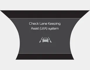
If there is a problem with the system a message will appear. If the problem continues the LKA system fail indicator will illuminate.
LKA system fail indicator
The LKA system fail indicator (yellow) will illuminate with an audible warning if the LKA system is not working properly. In this case, have the system checked by an authorized Kia dealer.
When there is a problem with the system do one of the following:
- Turn the system on after turning the engine off and on again.
- Check if the ignition switch is in the ON position.
- Check if the system is affected by the weather. (ex: fog, heavy rain, etc.)
- Check if there is foreign matter on the camera lens
If the problem is not solved, have the system checked by an authorized Kia dealer.
Other information:
Kia Stinger (CK) 2018-2023 Owner's Manual: Inside Rear View Mirror
Components and components location Component Location 1. Inside rear view mirror Repair procedures Replacement Put on gloves to protect your hands. • Use a plastic panel removal tool to remove interior trim pieces without marring the surface.Components and components location Components 1. Engine mounting support bracket (LH) 2. Engine mounting support bracket (RH) 3. Engine mounting bracket (LH) 4. Engine mounting bracket (RH) 5. Transmission mounting bracket (AWD) 6. Transmission mounting bracket (2WD) Repair procedures Removal and Installation Engine Mounting Bracket 1.Categories
- Manuals Home
- Kia Stinger Owners Manual
- Kia Stinger Service Manual
- New on site
- Most important about car
Contents
Copyright © 2026 www.kstinger.com 0.0114


