Kia Stinger CK: Intake And Exhaust System / Intercooler
Components and components location
| Components |
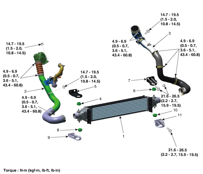
| 1. Intercooler 2. Intercooler inlet hose & pipe 3. Intercooler outlet hose & pipe 4. Intercooler upper mounting insulator (RH) 5. Intercooler upper mounting bracket (RH) 6. Intercooler upper mounting insulator (LH) |
7. Intercooler upper mounting
bracket (LH) 8. Intercooler lower mounting insulator (RH) 9. Intercooler lower mounting bracket (RH) 10. Intercooler lower mounting insulator (LH) 11. Intercooler lower mounting bracket (LH) |
Repair procedures
| Removal and Installation |
Intercooler Inlet Hose & Pipe
| 1. |
Remove the air intake hose. (Refer to Intake and Exhaust System - "Air Cleaner") |
| 2. |
Disconnect the recirculation valve connector (A) and the vacuum hose (B).
|

| 3. |
Remove the intercooler inlet hose & pipe assembly (A).
|

| 4. |
Remove the engine room front under cover. (Refer to Engine and Transmission Assembly - "Engine Room Under Cover") |
| 5. |
Remove the intercooler inlet hose (A).
|


| 6. |
Install in the reverse order of removal. |
Intercooler outlet Hose & Pipe
| 1. |
Disconnect the booster pressure sensor connector (A).
|

| 2. |
Remove the intercooler outlet hose & pipe assembly (A).
|

| 3. |
Remove the engine room front under cover. (Refer to Engine and Transmission Assembly - "Engine Room Under Cover") |
| 4. |
Remove the intercooler outlet hose (A).
|

| 5. |
Install in the reverse order of removal. |
Intercooler
| 1. |
Remove the engine room front under cover. (Refer to Engine and Transmission Assembly - "Engine Room Under Cover") |
| 2. |
Disconnect the intercooler inlet hose (A).
|
| 3. |
Disconnect the intercooler outlet hose (A).
|
| 4. |
Install the jack under the intercooler to support the intercooler.
|

| 5. |
Remove the intercooler lower mounting bracket (A).
[LH]
[RH]
|


| 6. |
Remove the intercooler (A).
|

| 7. |
Remove the intercooler upper mounting bracket (A).
[LH]
[RH]
|


| 8. |
Install in the reverse order of removal. |


Other information:
Description and operation Description 1. Function • By detecting the pressure, temperature, acceleration, and battery condition, transmit information to ECU by a wireless RF. • Wheel location is recognized by comparing the Wheel Pulse of ECS (ABS) and acceleration values of the sensor (High Line).Repair procedures Removal 1. Remove wheel nuts, wheel and tire (A) from hub. Tightening torque: 107.9 - 127.5 N·m (11.0 - 13.0 kgf·m, 79.6 - 94.0 lb·ft) Be careful not to damage the wheel bolts when removing the wheel and tire (A).Categories
- Manuals Home
- Kia Stinger Owners Manual
- Kia Stinger Service Manual
- New on site
- Most important about car
