Kia Stinger CK: Engine Control System / Engine Coolant Temperature Sensor (ECTS)
Specifications
| Specification |
|
Temperature |
Resistance (kΩ) |
|
|
°C |
°F |
|
|
-40 |
-40 |
48.14 |
|
-20 |
-4 |
14.13 - 16.83 |
|
0 |
32 |
5.79 |
|
20 |
68 |
2.31 - 2.59 |
|
40 |
104 |
1.15 |
|
60 |
140 |
0.59 |
|
80 |
176 |
0.32 |
Description and operation
| Description |
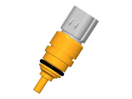
Located in the engine coolant passage of the cylinder head, Engine Coolant Temperature Sensor (ECTS) detects the engine coolant temperature. The ECTS uses a thermistor that changes resistance with the temperature.
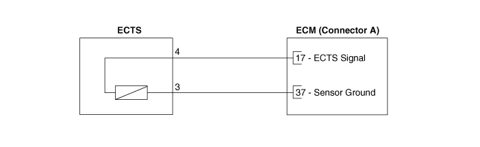
The electrical resistance of the ECTS decreases as the temperature increases, and increases as the temperature decreases. The reference +5V is supplied to the ECTS via a resistor in the ECM. That is, the resistor in the ECM and the thermistor in the ECTS are connected in series. When the resistance value of the thermistor in the ECTS changes according to the engine coolant temperature, the output voltage also changes.
During cold engine operation, the ECM increases the frequency of fuel injection and controls the ignition timing using the information of engine coolant temperature to avoid engine stalling and improve drivability.
Schematic diagrams
| Circuit Diagram |
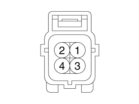
Harness Connector
Repair procedures
| Inspection |
| 1. |
Switch "OFF" the ignition. |
| 2. |
Remove the ECTS (Refer to "Removal"). |
| 3. |
After immersing the thermistor of the sensor into engine coolant, measure resistance between the ECTS terminals 3 and 4. |
| 4. |
Check that the resistance is within the specification.
|
||||||||||||||||||||||||||
| Removal |
| 1. |
Switch "OFF" the ignition and disconnect the negative (-) battery terminal. |
| 2. |
Remove the engine cover. (Refer to Engine Mechanical System - "Engine Cover") |
| 3. |
Remove the cowl top cover assembly. (Refer to Body (Interior and Exterior) - Cowl Top Cover") |
| 4. |
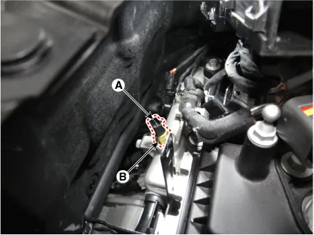
Disconnect the engine coolant temperature sensor connector (A). |
| 5. |
Remove the engine coolant temperature sensor (B) from the water temperature control assembly.
|
| Installation |
|

| 1. |
Install in the reverse order of removal. |
| 2. |
Replenish the engine coolant. (Refer to Engine Mechanical System - “Coolant”) |


Other information:
Kia Stinger (CK) 2018-2023 Service Manual: Emergency starting
Connect cables in numerical order and disconnect in reverse order. Jump starting Jump starting can be dangerous if done incorrectly. Therefore, to avoid harm to yourself or damage to your vehicle or battery, follow these jump starting procedures. If in doubt, we strongly recommend that you have a competent technician or towing service jump start your vehicle.Kia Stinger (CK) 2018-2023 Service Manual: Drive Belt Tensioner
Repair procedures Removal and Installation 1. Remove the drive belt. (Refer to Drive Belt System - "Drive Belt") 2. Remove the drive belt auto tensioner pulley (A). Tightening torque : 53.9 - 63.7 N·m (5.5 - 6.5 kg·m, 39.8 - 47.0 lb·ft) Tensioner pulley bolt is left-hands screw.Categories
- Manuals Home
- Kia Stinger Owners Manual
- Kia Stinger Service Manual
- New on site
- Most important about car
