Kia Stinger CK: Specifications & Consumer information
Contents:
- Dimensions, Engine, Bulb wattage
- Tires and wheels
- Gross vehicle weight, Luggage volume, Air conditioning system
- Recommended lubricants and capacities
- Vehicle Identification Number (VIN), Vehicle certification label
- Tire specification and pressure label, Engine number
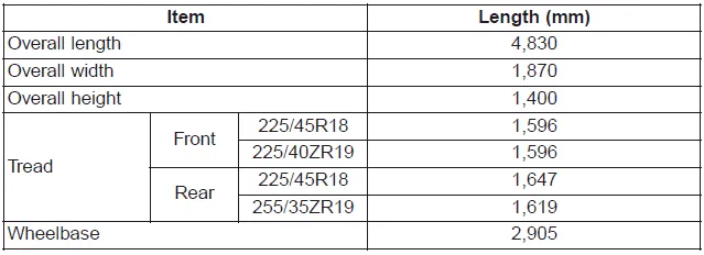
Dimensions, Engine, Bulb wattage
Dimensions
Engine

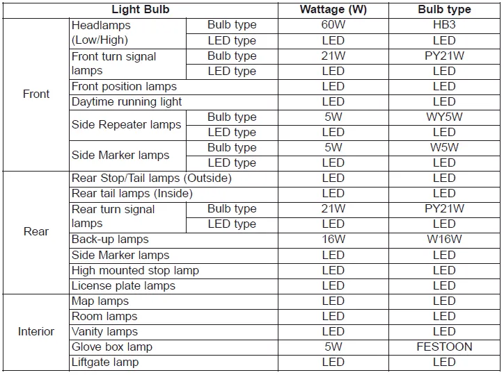
Bulb wattage
Tires and wheels
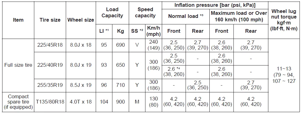
*1: Load Index
*2: Speed Symbol
*3: Normal load : Up to 3 persons
*4: It is applied to Lambda II PE 3.3L T-GDI AWD vehicle.
CAUTION
When replacing tires, use the same size originally supplied with the vehicle. Using tires of a different size can damage the related parts or make them work irregularly.
✽ NOTICE
- It is permissible to add 21 kPa (3 psi) to the standard tire pressure specification if colder temperatures are expected soon. Tires typically loose 7 kPa (1 psi) for every -11°C (12°F) temperature drop. If extreme temperature variations are expected, re-check your tire pressure as necessary to keep them properly inflated.
- We recommend that when replacing tires, use the same originally supplied with the vehicles. If not, that affects driving performance.
- When driving in high altitude grades, it is natural for the atmospheric pressure to decrease. Therefore, please check the tire pressure and add more air when necessary. Additionally required tire air pressure per km above sea level: 10.5 kPa (1.5 psi)/km
- Speeds above 160 km/h (100 mph) In order to drive at maximum speeds in excess of 160 km/h (100 mph), please observe, and, if necessary, adjust tire pressures for speeds exceeding 160 km/h (100 mph) from the above table. Otherwise tire damage and accidents could occur.
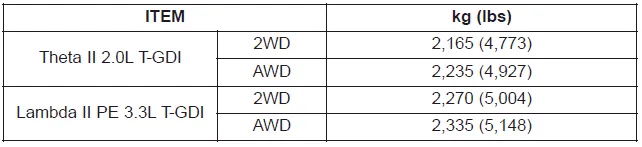
Gross vehicle weight, Luggage volume, Air conditioning system
Gross vehicle weight
Luggage volume

Air conditioning system
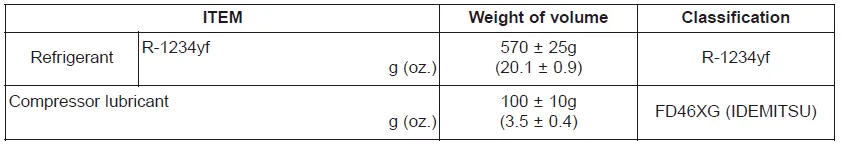
We recommend that you contact an authorized Kia dealer for more details.
Recommended lubricants and capacities ➤
Vehicle Identification Number (VIN), Vehicle certification label
Vehicle Identification Number (VIN)
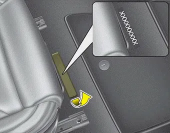
■ Frame number
The vehicle identification number (VIN) is the number used in registering your vehicle and in all legal matters pertaining to its ownership, etc.
The number is punched under driver or front passenger seat.
To check the number, open the cover.
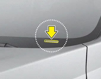
■ VIN label
The VIN is also on a plate attached to the top of the dashboard. The number on the plate can easily be seen through the windshield from outside.
Vehicle certification label
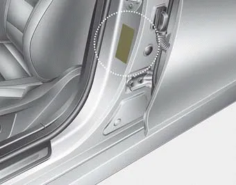
The vehicle certification label attached on the driver’s side center pillar gives the vehicle identification number (VIN).
Tire specification and pressure label, Engine number
Tire specification and pressure label

The tires supplied on your new vehicle are chosen to provide the best performance for normal driving.
The tire label located on the driver's side center pillar gives the tire pressures recommended for your vehicle.
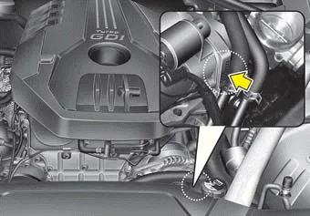
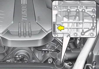
Engine number
■ Gasoline engine (Theta II 2.0L T-GDI)
■ Gasoline engine (Lambda II PE 3.3L T-GDI)
The engine number is stamped on the engine block as shown in the drawing.