Kia Stinger CK: Towing / Towing service
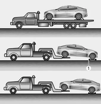
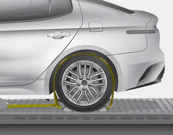
If emergency towing is necessary, we recommend having it done by an authorized Kia dealer or a commercial tow-truck service. Proper lifting and towing procedures are necessary to prevent damage to the vehicle. The use of wheel dollies(1) or flatbed is recommended.
On AWD vehicles, your vehicle must be towed with a wheel lift and dollies or flatbed equipment with all the wheels off the ground.
CAUTION
The AWD vehicle should never be towed with the wheels on the ground. This can cause serious damage to the transaxle or the AWD system.
If any of the loaded wheels or suspension components are damaged or the vehicle is being towed with the front wheels on the ground, use a towing dolly under the front wheels.
When being towed by a commercial tow truck and wheel dollies are not used, the rear of the vehicle should always be lifted, not the front.
✽ NOTICE
If the EPB does not release normally, take your vehicle to an authorized Kia dealer by loading the vehicle on a flatbed tow truck and have the system checked.
- Ensure any metal parts on the tiedown straps do not contact painted surfaces or the face of the wheels.
- Do not place straps over the body panels or through the wheels.
CAUTION
Attaching straps to the chassis, suspension or other parts of the body can cause damage.
WARNING - Side and curtain Air bag
If your vehicle is equipped with side and curtain air bag, set the the Engine Start/Stop button to ACC position when the vehicle is being towed. The side and curtain air bag may deploy when the ignition is ON, and the rollover sensor detects the situation as a rollover.
CAUTION - Towing
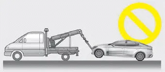
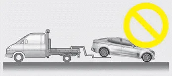
- Do not tow the vehicle backwards with the rear wheels on the ground as this may cause damage to the vehicle.
- Do not tow with sling-type equipment. Use wheel lift or flatbed equipment.
When towing your vehicle in an emergency without wheel dollies :
1. Set the Engine Start/Stop button to ACC position.
2. Place the transaxle shift lever in N (Neutral).
3. Release the parking brake.
CAUTION - Towing gear position
Failure to place the transaxle shift lever in N (Neutral) may cause internal damage to the transaxle.


Other information:
Repair procedures Replacement Put on gloves to protect your hands. • Use a plastic panel removal tool to remove interior trim pieces without marring the surface.Average Fuel Economy (1) The average fuel economy is calculated by the total driving distance and fuel consumption since the last average fuel economy reset. - Fuel economy range: 0.0 ~ 99.9 L/100km or MPG The average fuel economy can be reset both manually and automatically. ✽ NOTICE The fuel economy may vary significantly based on driving conditions, driving habits, and condition of the vehicle.Categories
- Manuals Home
- Kia Stinger Owners Manual
- Kia Stinger Service Manual
- New on site
- Most important about car
