Kia Stinger CK: Brake system / AUTO HOLD
Contents:
The Auto Hold maintains the vehicle in a standstill even though the brake pedal is not depressed after the driver brings the vehicle to a complete stop by depressing the brake pedal.

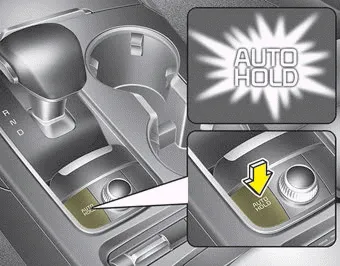
1.Depress the brake pedal, start the engine and then press the Auto Hold button. The white AUTO HOLD indicator will come on indicating the system is in standby.
Before the Auto Hold will engage, the driver's door and engine hood must be closed and the driver's seat belt must be fastened.

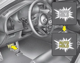
2.When coming to a complete stop by depressing the brake pedal, the AUTO HOLD indicator changes from white to green indicating the AUTO HOLD is engaged. The vehicle will remain at a standstill even if you release the brake pedal.
3.If EPB is applied, Auto Hold will be released.
4. If you press the accelerator pedal with the shift lever in D (Drive) or manual mode, the Auto Hold will be released automatically and the vehicle will start to move. The indicator changes from green to white indicating the Auto Hold is in standby and the EPB is released.
When driving off from Auto Hold by depressing the accelerator pedal, always check the surrounding area near your vehicle.
Slowly depress the accelerator pedal for a smooth launch.
Cancel

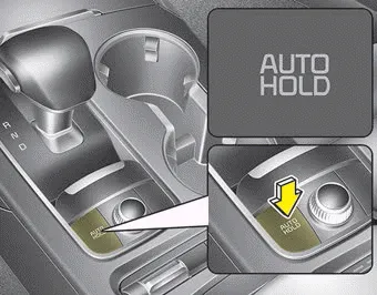
To cancel the Auto Hold operation, press the Auto Hold switch. The AUTO HOLD indicator will go out.
To cancel the Auto Hold operation when the vehicle is at a standstill, press the Auto Hold switch while depressing the brake pedal.
✽ NOTICE
- The following are conditions when the Auto Hold will not engage (Auto Hold
light will not turn green and the Auto Hold system remains in stand by):
- The driver's seat belt is unfastened and driver's door is opened
- The engine hood is opened
- The shift lever is in P (Park) or R (Reverse)
- The EPB is applied - For your safety, the Auto Hold automatically switches to EPB under any of
the following conditions (Auto Hold light remains white and the EPB automatically
applies):
- The driver's seat belt is unfastened and driver's door is opened
- The engine hood is opened
- The vehicle is in a standstill for more than 10 minutes
- The vehicle is standing on a steep slope
- The vehicle moved for a few seconds
In these cases, the brake warning light comes on, the AUTO HOLD indicator changes from green to white, and a warning sounds and a message will appear to inform you that EPB has been automatically engaged. Before driving off again, press foot brake pedal, check the surrounding area near your vehicle and release parking brake manually with the EPB switch. - If the AUTO HOLD indicator lights up yellow, the Auto Hold is not working properly. Take your vehicle to an authorized Kia dealer and have the system checked.
If there is a malfunction with the driver's door or engine hood open detection system, the Auto Hold may not work properly.
Take your vehicle to an authorized Kia dealer and have the system checked.
✽ NOTICE
A click or electric brake motor whine sound may be heard while operating or releasing the EPB, but these conditions are normal and indicate that the EPB is functioning properly.
Other information:
Kia Stinger (CK) 2018-2023 Owner's Manual: Front Disc Brake
Components and components location Components [Standard] 1. Caliper housing 2. Brake member 3. Brake pad assembly [IN] 4. Retainer 5. Brake pad assembly [OUT] 6. Brake pad return spring [Brembo] 1. Caliper housing 2. Brake pad cover 3. Brake pad 4.Kia Stinger (CK) 2018-2023 Owner's Manual: Climate Control Air Filter
Description and operation Description Located in the blower unit, the climate control air filter eliminates foreign materials and odor. The particle filter performs the roles of an odor filter as well as a conventional dust filter to ensure pleasant interior environment. Repair procedures Replacement 1. Remove the stopper (B) from the glove box (A).Categories
- Manuals Home
- Kia Stinger Owners Manual
- Kia Stinger Service Manual
- New on site
- Most important about car


