Kia Stinger CK: Driving your vehicle / Blind-spot Collision Warning (BCW)
Contents:
The Blind-Spot Collision Warning (BCW) system uses radar sensors in the rear bumper to monitor and warn the driver of an approaching vehicle in the driver's blind spot area.
The system monitors the rear area of the vehicle and provides information to the driver with an audible alert and a indicator on the outside rearview mirrors.
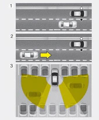
(1) Blind spot area
The BCW range varies relative to vehicle speed. Note that if your vehicle is traveling much faster than the vehicles around you, the warning will not occur.
(2) Closing at high speed
The BCW-Closing at high speed feature will alert you when it detects a vehicle is approaching in an adjacent lane at a high rate of speed. If the driver activates the turn signal when the system detects an oncoming vehicle, the system sounds an audible alert.
(3) RCCW (Rear Cross-Traffic Collision Warning)
The RCCW feature monitors approaching cross traffic from the left and right side of the vehicle when your vehicle is in reverse. The feature will operate when the vehicle is moving in reverse below about 10 km/h (6 mph). If oncoming cross traffic is detected a warning chime will sound.
WARNING - BCW Limitations
- The Blind-Spot Collision Warning System (BCW) is a supplemental system. Do not solely rely on the system and always pay attention to drive safely.
- The Blind-Spot Collision Warning System may not detect every object alongside the vehicle and is not a substitute for proper and safe lane changing procedures. Always drive safely and use caution when changing lanes.
BCW (Blind-Spot Collision Warning) ➤
RCCW (Rear Cross-Traffic Collision Warning) ➤
Driver's Attention ➤


Other information:
Kia Stinger (CK) 2018-2023 Owner's Manual: Forward Collision-Avoidance Assist (FCA) System
Description and operation Description – The Forward Collision-Avoidance Assist (FCA) radar sends a signal to detect the vehicle in front, based on the calculated distance the FCA applies the brakes in order to avoid or lessen collision with the vehicle in front due driver distraction or late braking response.Kia Stinger (CK) 2018-2023 Owner's Manual: Steering Gear Rack, Linkage and Boots
Repair procedures Inspection 1. Check the steering wheel free road. (1) Turn the steering wheel so that the front wheels are facing straight ahead. (2) Measure the distance where the steering wheel can be turned without moving the front wheels.Categories
- Manuals Home
- Kia Stinger Owners Manual
- Kia Stinger Service Manual
- New on site
- Most important about car
Contents
