Kia Stinger: Head Up Display (HUD) System / Head Up Display (HUD) Unit
Components and components location
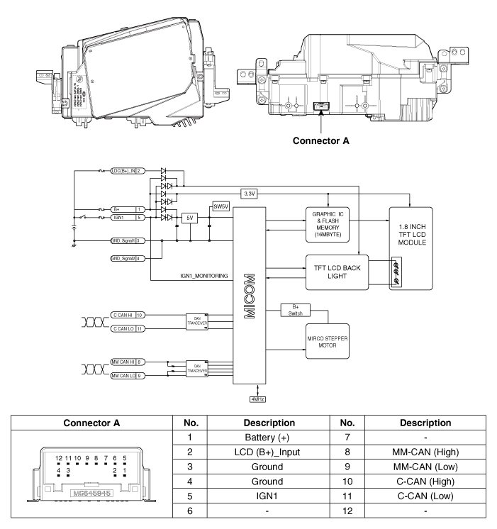
Repair procedures
|
Put on gloves to prevent hand injuries.
|
| • |
Use a plastic panel removal tool to remove interior trim pieces
without marring the surface.
|
| • |
Take care not to bend or scratch the trim and panels.
|
|
| 1. |
Disconnect the negative (-) battery terminal.
|
| 2. |
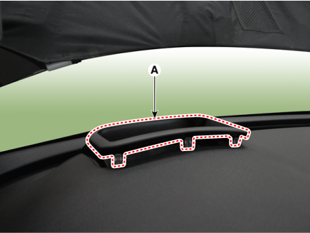
Remove the head up display bezel (A) by using a remover.
|
| 3. |
Remove the instrument cluster.
(Refer to Indicators And Gauges - "Instrument Cluster")
|
| 4. |
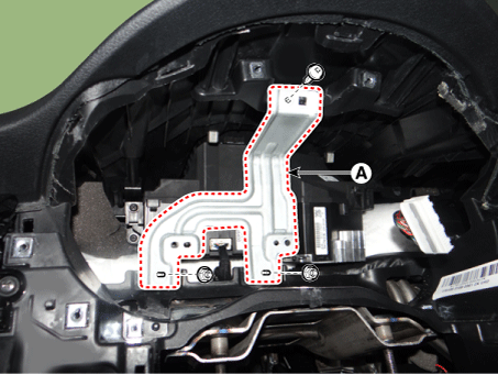
Remove the head up display unit bracket (A) after loosening the mounting
screw and nuts.
|
| 5. |
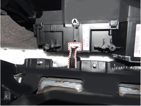
Disconnect the head up display unit connector (A).
|
| 6. |
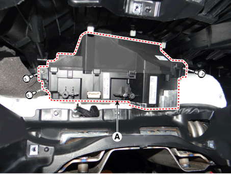
Remove the head up display unit (A) after loosening the mounting screws.
|
| 1. |
Connect the connector after installing the head up display unit.
|
| 2. |
Install the head up display unit bracket.
|
| 3. |
Install the instrument cluster.
|
| 4. |
Install the head up display bezel.
|
| 5. |
Connect the negative (-) battery terminal.
|
If a part of the head up display footage is distorted or it is not at eye level
with the driver a Global Diagnostic System (KDS) can be used to carry out calibration.
| 1. |
Calibration is required:
| – |
After replacing the head-up display unit
|
| – |
When the footage is distorted after replacing the windshield
(double vision removal film built-in glass)
|
| – |
When the HUD mounted main crashpad is removed/installed or replaced.
|
| – |
When the image setting location of the HUD unit is not at eye
level of the driver resulting in out of focus image.
|
|
| 2. |
Calibration items
No
|
Footage calibration functions
|
Calibration cases
|
1
|
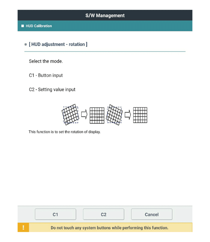
Rotation: Calibrate in counterclockwise/clockwise direction at the
center.
|

|
2
|
Smile: Calibrate vertically at the center.
|

|
3
|
Slanted (up/down): Calibrate along a vertical inclination.
|

|
4
|
Slanted (left/right): Calibrate along a horizontal inclination.
|

|
5
|
Parallel compensation
|

|
6
|
Up/down movement of indicated location: Calibrate to user eye level.
|

|
7
|
Initialization: Return to previous status before calibration.
|
|
|
| 3. |
Process of calibration
| (1) |
Locate the vehicle on a flat plane for accurate adjustment.
|
| (2) |
Make sure that there are no foreign materials on the windshield.
|
| (3) |
Connect the Global Diagnostic System to the vehicle, and select
vehicle type and HUD system additional functions.
|
| (4) |
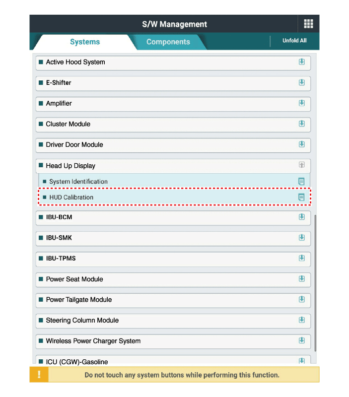
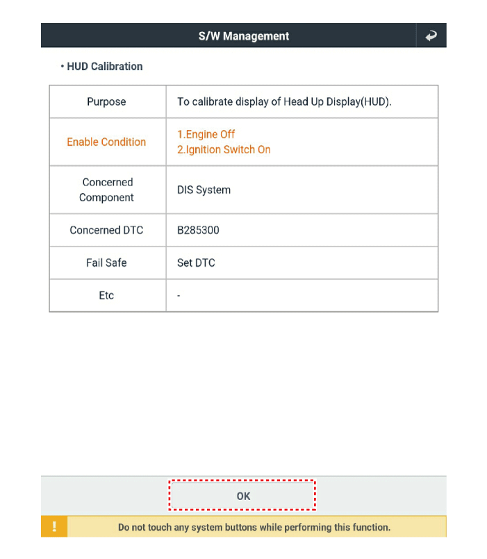
Under additional functions select 'HUD calibration'.
|
| (5) |
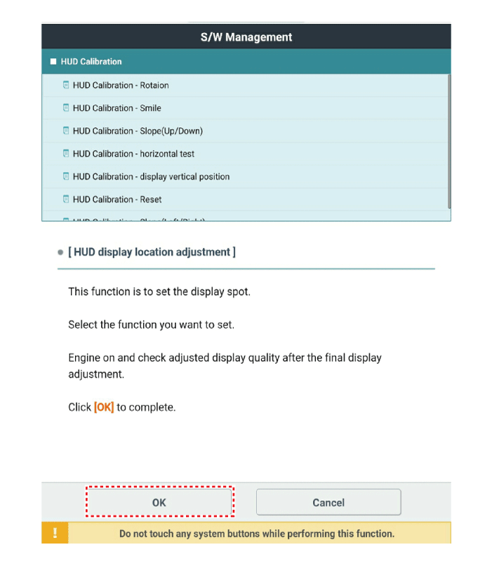
Before 'calibration', carry out 'HUD calibration - initialization'.
|
'HUD calibration - initialization' must be performed
prior to 'calibration'.
|
|
| (6) |
Select the necessary calibration items and carry out 'HUD calibration'.
|
| (7) |
When calibration is completed, start and cut off the engine and
check that the footage calibration is completed.
|
|
Troubleshooting
Category
|
Error symptoms
|
Inspection item
|
Detailed inspection item
|
Related parts
|
Lighting
|
| • |
Lighting brightness not automatically controlled (no difference
between day and night)
|
|
| • |
Check the lighting control
|
| • |
Check the ambient light sensor operation
|
| • |
Check the CAN communication
|
|
| • |
Check the lighting control in the cluster USM
→ If working, HUD has no problem.
|
| • |
Check the ambient light sensor operation
→ If the ambient light sensor works, check the communications
(CGW ↔ HUD)
|
|
Light sensor
CGW
Cluster
|
Adjustment function
|
| • |
Display position not adjusted
|
|
| • |
Check the mirror movement when IG is on or off (parking position)
|
|
| • |
If the step motor does not work when IG is on or off,
→ The step motor in HUD fails.
|
| • |
If the step motor in HUD works when IG is on or off,
→ Check the CAN communications (cluster ↔ HUD)
|
|
HUD
Cluster
|
Components and components location
Components Location
1. Head Up Display (HUD)
2. Ambient light sensor
3. Cluster (User setting menu
ON/OFF, Display brightn ...
Components and components location
Components
1. LKA ON/OFF switch
2. Instrument cluster
3. LKA Unit (MFC)
* MFC : Multi Function Camera
†...
Other information:
If the driver turns off the engine when the sunroof is not fully closed, the
warning chime will sound for a few seconds and the above warning illustration will
appear on the LCD display.
Close the sunroof securely when leaving your vehicle.
CAUTION
Make sure the sunroof is fully closed when ...
If the tire is worn evenly, a tread wear Indicator (A) will appear as a solid
band across the tread. This shows there is less than 1.6 mm (1/16 inch) of tread
left on the tire. Replace the tire when this happens.
Do not wait for the band to appear across the entire tread before replacing the ...

 Head Up Display (HUD) System
 Lane Keeping Assist (LKA)


