Kia Stinger: Windshield Wiper/Washer
Components and components location
| Component Location |
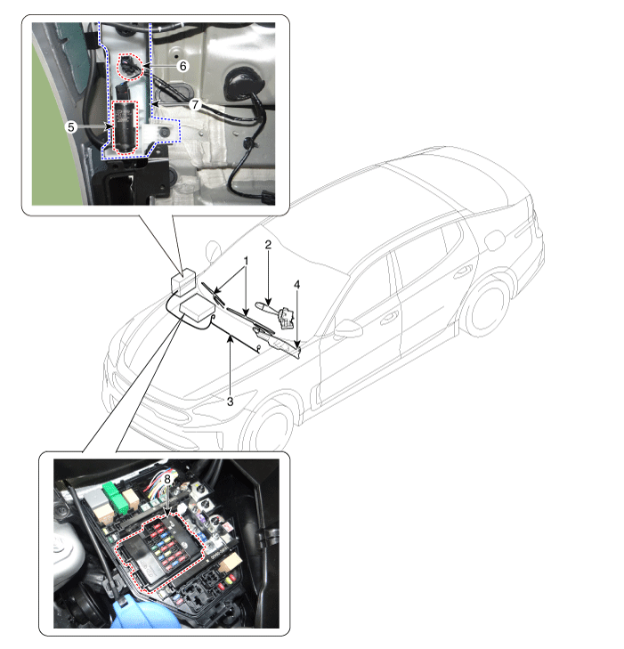
| 1. Windshield wiper arm & blade
2. Wiper & washer switch 3. Windshield washer hose & nozzle 4. Wiper motor & linkage assembly |
5. Washer motor 6. Washer fluid level sensor 7. Washer reservoir tank 8. Wiper/Washer relay (Built-in Metal core block PCB) |
Windshield Wiper-Washer Switch
Repair procedures
| Removal |
| 1. |
Disconnect the negative (-) battery terminal. |
| 2. |
Remove the steering wheel. (Refer to Steering System - "Steering Wheel") |
| 3. |
Remove the steering column upper and lower shrouds after loosening the screws. (Refer to Body - "Steering Column Shroud Panel") |
| 4. |
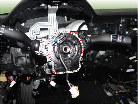
Remove the clock spring. (Refer to Restraint - "Driver Airbag (DAB) Module and Clock Spring")
|
| 5. |
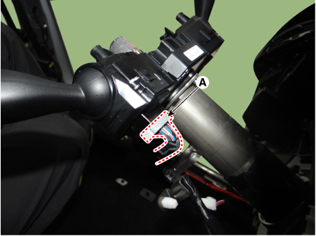
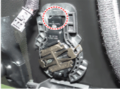
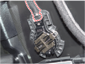
Disconnect the multifunction switch connector (A).
|
| 6. |
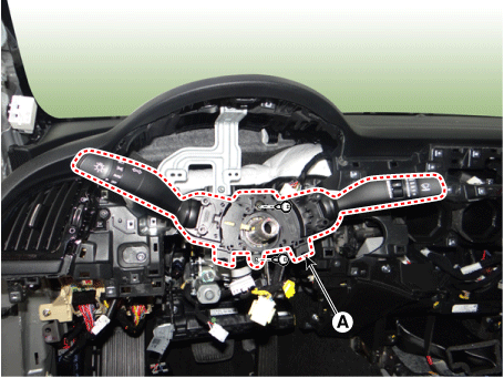
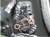
Remove the multifunction switch assembly (A) after loosening the mounting screws.
|
| Installation |
| 1. |
Install the multifunction switch. |
| 2. |
Install the clock spring. |
| 3. |
Install the steering column upper and lower shrouds. |
| 4. |
Install the steering wheel. |
| 5. |
Connect the negative (-) battery terminal. |
| Inspection |
Multifunction Switch Inspection
| 1. |
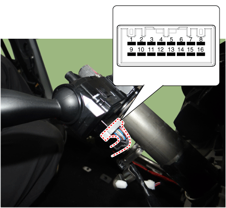
Check for continuity between the terminals in each switch position as shown below.
[Left Handle Drive]
[Right Handle Drive]
|
Inspection (With KDS)
| 1. |
In the body electrical system, failure can be quickly diagnosed by using the vehicle diagnostic system (KDS). The diagnostic system(KDS) provides the following information.
|
| 2. |
Select the 'Car model' and the 'Intergrated body control unit (IBU)' to be checked in order to check the vehicle with the tester. |
| 3. |
Select the 'Current Data' menu to search the current state of the input/output data. |
Front Wiper Motor
Components and components location
| Component Location |
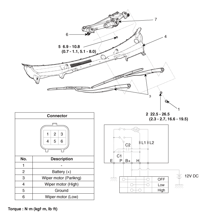
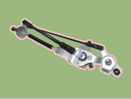
| 1. Cap 2. Nut 3. Wiper arm & blade 4. Cowl top cover |
5. Bolt / Nut 6. Wiper motor & linkage assembly 7. Wiper motor connector |
Repair procedures
| Removal |
| 1. |
Disconnect the negative (-) battery terminal. |
| 2. |
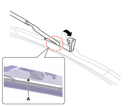
If necessary, release the wiper blade fixing clip by pulling up and remove the wiper blade from the inside radius (A) of wiper arm.
|
| 3. |
Remove the cowl top cover. (Refer to Body - "Cowl Top Cover") |
| 4. |
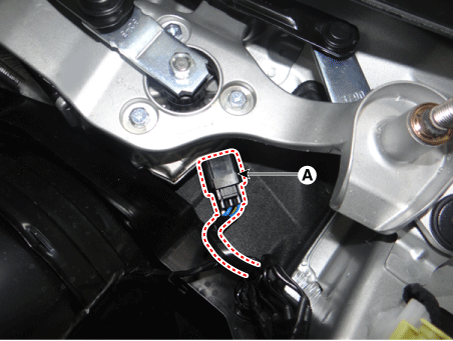
Disconnect the wiper motor connector (A).
|
| 5. |
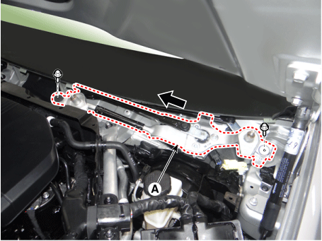
Remove the wiper motor & linkage assembly (A) after loosening the mounting bolts and nut.
|
| 6. |
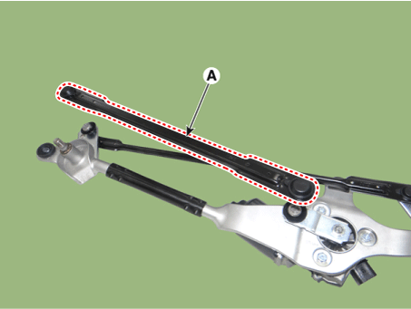
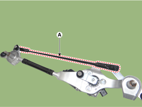
Hold the wiper motor crank arm and remove the upper linkage (A).
|
| 7. |
Remove the lower linkage (A) from the wiper motor crank arm.
|
| 8. |
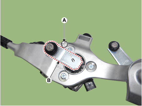
Remove the crank arm (B) after loosening a nut (A).
|
| 9. |
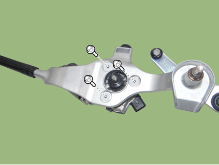
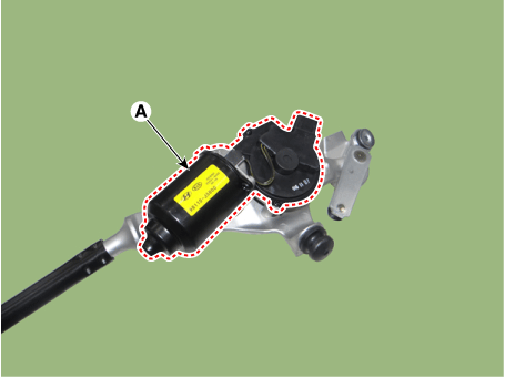
Remove the wiper motor (A) after loosening the mounting bolts.
|
| Installation |
| 1. |
Install the wiper motor. |
| 2. |
Install the crank arm.
|
| 3. |
Install the lower and upper linkage to the wiper motor crank arm. |
| 4. |
Install the wiper motor and linkage assembly and then connect the wiper motor connector.
|
| 5. |
Install the cowl top cover. |
| 6. |
Install the windshield wiper arm and blade.
|
| 7. |
Install the wiper arm and blade to the specified position. Auto stop position (Blade)
|
| Inspection |
| 1. |
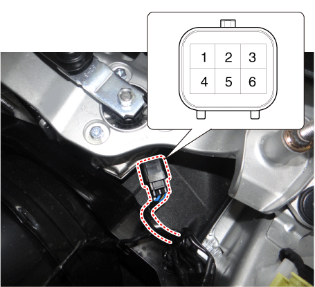
Remove the connector from the wiper motor.
|
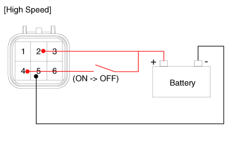
| 2. |
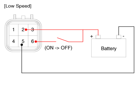
Attach the positive (+) lead from the battery to terminal 2 and the negative (-) lead to terminal 5.
|
| Inspection (With KDS) |
| 1. |
In the body electrical system, failure can be quickly diagnosed by using the vehicle diagnostic system (KDS). The diagnostic system(KDS) provides the following information.
|
| 2. |
Select the 'Car model' and the 'Intergrated body control unit (IBU)' to be checked in order to check the vehicle with the tester. |
| 3. |
Select the 'Current Data' menu to search the current state of the input/output data. |
Front Washer Motor
Repair procedures
| Inspection |
Front Washer Motor
| 1. |
With the washer motor connected to the reservoir tank, fill the reservoir tank with water.
|
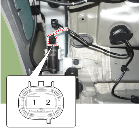
| 2. |
Connect positive (+) battery cables to terminal 2 and negative (-) battery cables to terminal 1 respectively. |
| 3. |
Check that the motor operates normally and the washer motor runs and water sprays from the front nozzles. |
| 4. |
If they are abnormal, replace the washer motor.
|
Washer Fluid Level Sensor Switch
| 1. |
Disconnect the negative (-) battery terminal. |
| 2. |
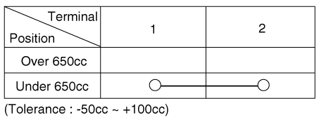
Drain the washer fluid less than 650 cc. |
| 3. |
Check for continuity between the No. 1 and No.2 terminal in each float position. There should be continuity when the float is down. There should be no continuity when the float is up. |
| 4. |
If the continuity is not as specified, replace the washer fluid level switch
|
| 5. |
If the continuity is not as specified, replace the washer fluid level switch. |
| Removal |
Front Washer Motor
| 1. |
Disconnect the negative (-) battery terminal. |
| 2. |
Remove the engine room under cover. D 2.2 R VGT (Refer to Engine Mechanical System - "Engine Room Under Cover") G 2.0 T-GDI THETA II (Refer to Engine Mechanical System - "Engine Room Under Cover") G 3.3 T-GDI LAMBDA II (Refer to Engine Mechanical System - "Engine Room Under Cover") |
| 3. |
Remove the front wheel guard [RH]. (Refer to Body - "Front Wheel Guard") |
| 4. |
Drain the washer fluid to less than 650 cc. |
| 5. |
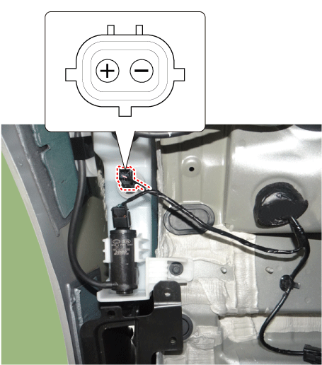
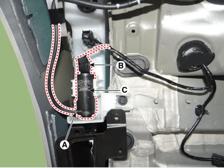
Disconnect the washer hose (A) and washer motor connector (B). |
| 6. |
Remove the front washer motor (C).
|
Washer Fluid Level Sensor Switch
| 1. |
Disconnect the negative (-) battery terminal. |
| 2. |
Remove the engine room under cover. D 2.2 R VGT (Refer to Engine Mechanical System - "Engine Room Under Cover") G 2.0 T-GDI THETA II (Refer to Engine Mechanical System - "Engine Room Under Cover") G 3.3 T-GDI LAMBDA II (Refer to Engine Mechanical System - "Engine Room Under Cover") |
| 3. |
Remove the front wheel guard [RH]. (Refer to Body - "Front Wheel Guard") |
| 4. |
Drain the washer fluid to less than 650 cc. |
| 5. |
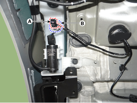
Remove the washer fluid level sensor switch (B) after disconnecting the connector (A).
|
Reservoir Tank
| 1. |
Disconnect the negative (-) battery terminal. |
| 2. |
Remove the front bumper assembly. (Refer to Body - "Front Bumper Assembly") |
| 3. |
Remove the front wheel guard [RH]. (Refer to Body - "Front Wheel Guard") |
| 4. |
Drain the washer fluid to less than 650 cc. |
| 5. |
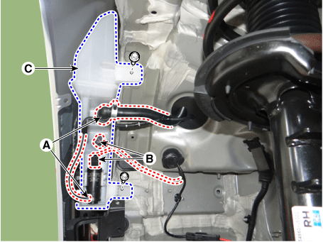
Disconnect the washer hoses (A) and connector (B). |
| 6. |
Remove the reservoir tank (C) after loosening the bolts.
|
| Installation |
Front Washer Motor
| 1. |
If necessary, clean the washer motor filter.
|
| 2. |
Install the front washer motor. |
| 3. |
Connect the front washer motor connector. |
| 4. |
Install the front wheel guard [RH]. |
| 5. |
Install the engine room under cover. |
| 6. |
Connect the negative (-) battery terminal. |
Washer Fluid Level Sensor Switch
| 1. |
If necessary, clean the washer motor filter.
|
| 2. |
Install the washer fluid level sensor switch. |
| 3. |
Connect the washer fluid level sensor switch connector. |
| 4. |
Install the front wheel guard [RH]. |
| 5. |
Install the engine room under cover. |
| 6. |
Connect the negative (-) battery terminal. |
Reservoir Tank
| 1. |
If necessary, clean the washer motor filter.
|
| 2. |
Install the reservoir tank. |
| 3. |
Install the washer motor hose and connectors. |
| 4. |
Install the front wheel guard [RH]. |
| 5. |
Install the front bumper assembly. |
| 6. |
Connect the negative (-) battery terminal. |
Rain Sensor
Components and components location
| Components and Components Location |
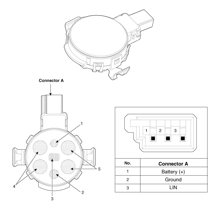
| 1. Horizontal light sensor
2. Vertical light sensor 3. Solar load sensor |
4. Rain sensor (Left) 5. Rain sensor (Right) |
Schematic diagrams
| Circuit Diagram |
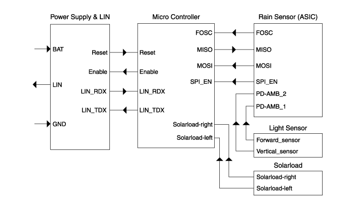
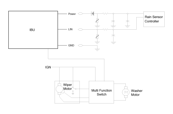
Description and operation
| Description |
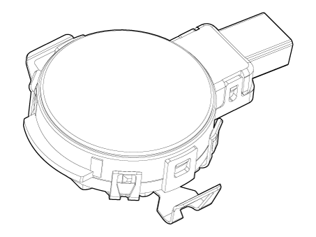
| Integrated Rain Sensor |
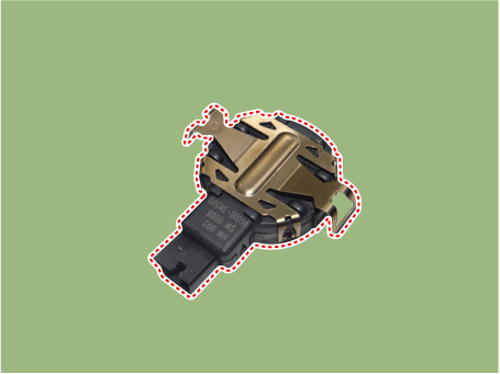
Integrated rain sensor (A) controls three systems: front wiper, auto-light, and central air conditioner.
| 1. |
Wiper Control System When "AUTO" switch signal is received from the multi-function switch on the right, the integrated rain sensor detects the amount of rainfall. The sensor is installed inside the upper part of the front window for wiper motor control. This system automatically controls the operation duration and speed of the wiper depending on the measured amount of rainfall even if the driver does not operate the wiper switch. |
| 2. |
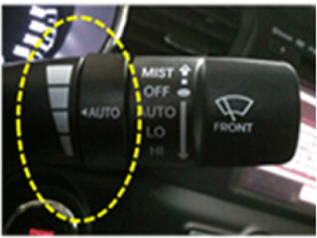
Auto Light Control System When "AUTO" signal is received from the multi-function switch on the left, the integrated rain sensor installed on the front window detects the brightness of the light and controls the operation of the head lamp and screen brightness of the internal multimedia. This system automatically controls the brightness of the head lamp and the internal multimedia screen depending on the measured brightness even if the driver does not operate the lamp switch. |
| 3. |
Central Air Conditioning System When "AUTO" signal is received from the central air conditioner switch, the integrated rain sensor detects the amount of sunshine depending on the direction of the sunlight. This system automatically controls the cooling system depending on the measured amount of sunshine even if the driver does not operate the air conditioner switch. |
| Functions and Operating Principles |
Basic Principle
| 1. |
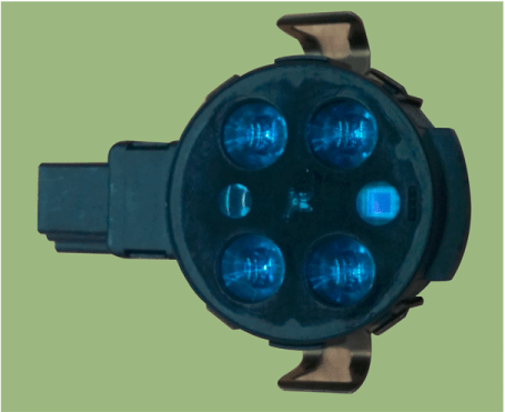
Detecting the amount of rainfall The light (beam) emitted from light emitting diodes (LED) is totally reflected on the external surface of the windshield and comes back to the photo diodes. When there is water on the external surface of the windshield, the light is optically separated and reflected partially and the remaining brightness is measured by the photo diodes. Water remaining on the windshield results in the light being not totally reflected. The loss of brightness due to this indicates how much the glass surface is wet. |
| 2. |
Detecting light Brightness of light is measured by the diodes using the infrared light. The brightness of the outside of the vehicle is measured in two directions: (a) the upper direction and (b) the front direction. The measured amount of light is used to determine whether it is day or night. |
| 3. |
Detecting the amount of sunshine The system measures the amount of sunshine from the left and right sides and operates the air conditioner on the driver side or the passenger side. |
Integrated rain sensor is composed of 2 LEDs and 2 photo diodes to detect rainfall, 2 photo diodes to detect light, 1 photo diode to detect the amount of sunshine, and bracket. |
Operation Control
| 1. |
When "AUTO" signal is received from the multi-function switch on the right, the integrated rain sensor detects the rainfall and controls the wiper motor. |
| 2. |
When “AUTO” signal is received from the multi-function switch on the left, the integrated rain sensor detects the brightness and controls the head lamp and internal multimedia brightness. |
| 3. |
When “AUTO” signal is received from the central air conditioner switch, the integrated rain sensor detects the amount of sunshine and controls the air conditioning system. |
Interference
Integrated rain sensor might malfunction due to the interferences listed below.
| 1. |
Dust on the measuring surface and other surfaces on the light path (surface of light emitting diodes and photo diodes, fiber optics, bracket, and glass surface of windshield joint area) weakens the received light. |
| 2. |
Movement of windshield and bracket |
| 3. |
Movement of bracket due to vibration |
| 4. |
Damaged wiper blade |
| 5. |
Damaged head lamp |
| 6. |
Damaged multimedia device |
| 7. |
Damaged air conditioning system |
When the integrated rain sensor does not operate or malfunctions, the driver should operate the wiper switch manually. When the integrated rain sensor does not operate or malfunctions, the driver should operate the head lamp switch manually. When the integrated rain sensor does not operate or malfunctions, the driver should operate the air conditioner switch manually. |
Automatic Operation
| 1. |
Operational status of rain sensor
|
| 2. |
Operational status of light sensor
|
| 3. |
Operational status of solar load sensor
|
Safety Function High
| 1. |
When there is ice or foreign substance in the detecting area, integrated rain sensor cannot recognize the condition for operation correctly. |
Detecting Special Conditions
| 1. |
Rain sensor
|
| 2. |
Light sensor
|
Repair procedures
| Inspection |
| Check point for rain sensor: |
| 1. |
To properly adjust sensitivity if auto wiping operates sensitively or insensitively.
|
| 2. |
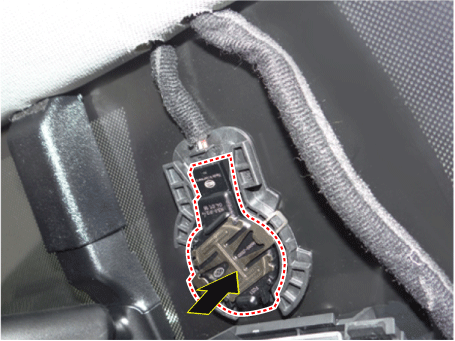
To check if a connector of sensor is normally connected
|
| 3. |
To check if sensor and bracket are normally connected. |
| 4. |
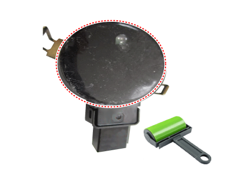
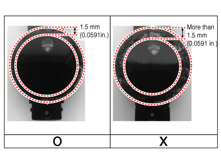
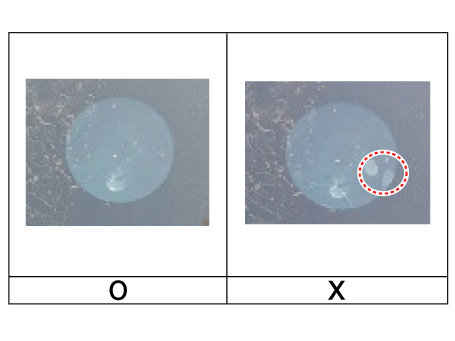
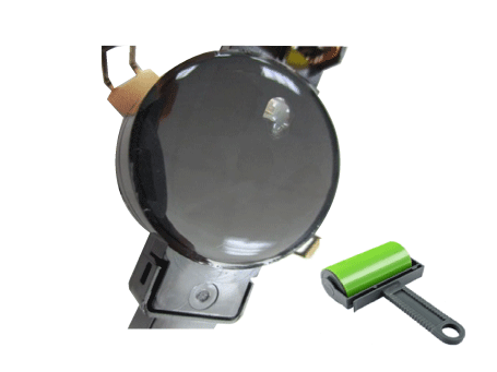
To check if sensor are contaminated by foreign substances (In case that silicone gel pad of rain sensor is polluted by foreign substances, rain sensor can be reusable after they are removed by sticker roller.)
|
| 5. |
To check if silicone gel pad on sensor is damaged.
|
Failure case
|
NO. |
Case |
Picture |
Status |
Remark |
|
1 |
Damage of silicone gel pad for rain sensor |
|
- Auto wiper does not operate intermittently |
Auto wiper does not activate according to damaged silicone gel pad range
|
|
2 |
Detached silicone gel pad from rain sensor |
|
- Auto wiper does not operate intermittently |
Auto wiper does not activate according to detached silicone gel pad range
|
|
3 |
Completely plugged-out rain sensor from wiring connector |
|
- Auto wiper does not activate - DTC code can be checked through diagnostic device |
DTC related with LIN communication error occurs |
|
4 |
Incompletely plugged-out rain sensor from wiring connector |
|
- Auto wiper does not operate intermittently - DTC code can be checked through diagnostic device |
DTC related with LIN communication error could occur if auto wiper does
not activate |
|
5 |
Clamp of rain sensor incompletely assembled with bracket |
|
- Auto wiper does not activate |
Auto wiper does not operate intermittently according to detached range from
windshield |
|
6 |
LIN communication error |
Rain sensor fault Communication fault |
- Auto wiper does not activate - DTC code can be checked through diagnostic device |
DTC related with LIN communication error occurs or caused by case 3 or case
4 |
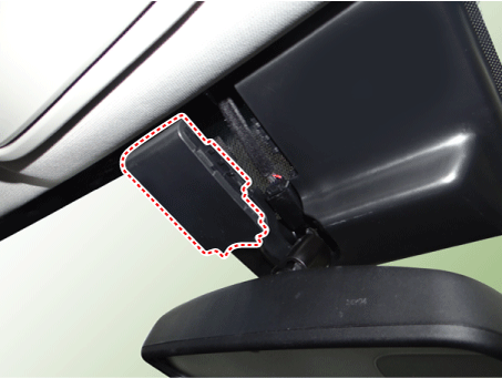
| Removal |
Caution for handling
|
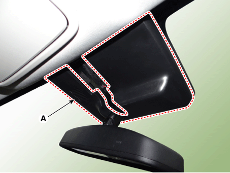
| 1. |
Remove the mirror wiring cover (A).
|
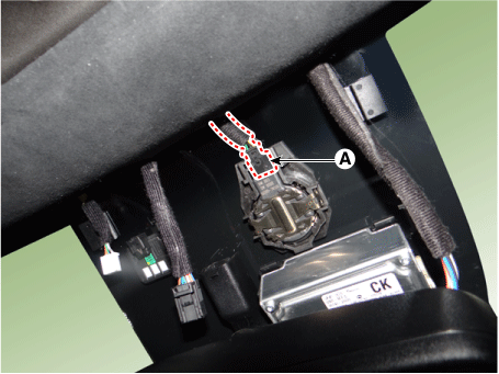
| 2. |
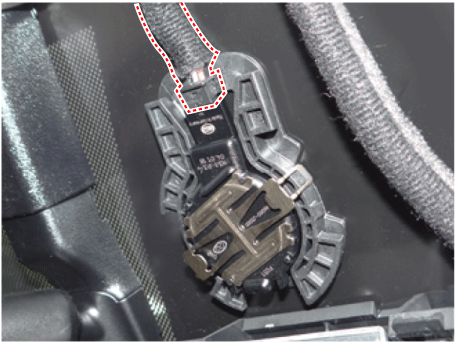
Disconnect the rain sensor connector (A).
|
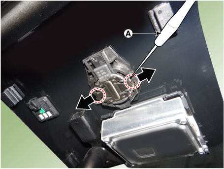
| 3. |
Be careful not to damage the cover latch by applying excessive force. To remove the bracket, pull the holes of the bracket outside using a small flat-head screwdriver (A).
|
| 4. |
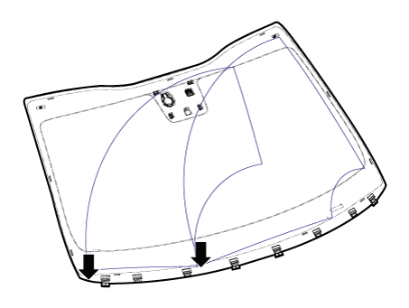
Rain sensor module is attached to the front windshield by glue. When replacing the front windshield, remove the rains sensor module form the existing front windshield and install it on the new front windshield. |
| Installation |
| 1. |
Install in the reverse order of removal.
|
| Replacement |
| Gel pad |
| 1. |
Remove the damaged silicone gel pad completely on the lens plate of rain sensor.
|
| 2. |
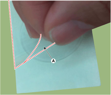
Remove the two protection foils (A) from the gel pad.
|
| 3. |
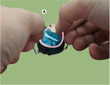
Attach the silicone gel pad (A) on the lens plate of rain sensor by hand.
|
- Emergency Call System
- Head Up Display (HUD) System
- Lane Keeping Assist (LKA)
- Wireless Power Charger (WPC) System
 Smart Key Diagnostic
Repair procedures
Inspection
1.
In the body electrical system, failure can be quickly diagnosed by using
the vehicle diagnostic system (KDS).
The diagnostic system ...
 Emergency Call System
Components and components location
Components
1. Head unit (AVN, Audio)
2. Emergency call button
3. Emergency call MIC
4. Roof antenna
5. Emergency call unit ...
Other information:
Kia Stinger CK 2018-2025 Service Manual: Disc Brakes and Pads
Repair procedures Inspection Check the pads for excessive wear, discs for run out and wear, and calipers for fluid leakage. Front Brake Front brake disc thickness check 1. Check the brake pads for wear and fade. 2. Check the ...
Kia Stinger CK 2018-2025 Service Manual: High Pressure Fuel Pump
Repair procedures Removal 1. Release the residual pressure in fuel line. (Refer to the Fuel Delivery System - "Release Residual Pressure in Fuel Line") 2. Switch "OFF" the ignition and disconnect the negative (-) battery ...

