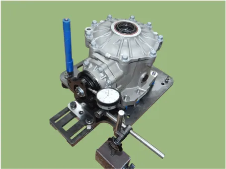
Kia Stinger CK: Differential Carrier Assembly / Front Differential Carrier
Repair procedures
| Removal |
| 1. |
Remove the propeller shaft. (Refer to Driveshaft and axle - "Front propeller shaft") |
| 2. |
Remove the sub frame. (Refer to Suspension System - "Sub frame") |
| 3. |
Separate the compressor. [LAMBDA II 3.3 T-GDI only] (Refer to Heating, Ventilation And Air Conditioning - "Compressor") |
| 4. |
Remove the front driveshaft. (Refer to Driveshaft and axle - "Front drive shaft") |
| 5. |
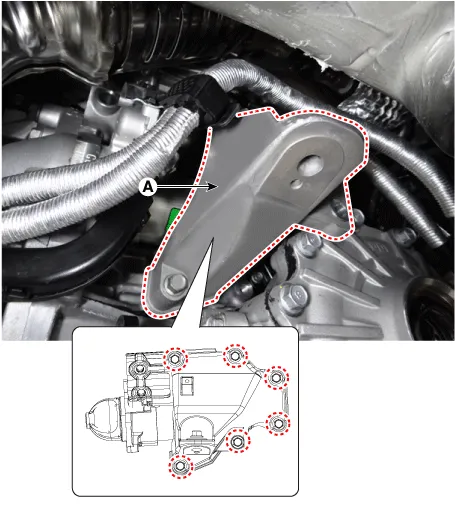
Remove the engine support bracket (A). [RH]
|
| 6. |
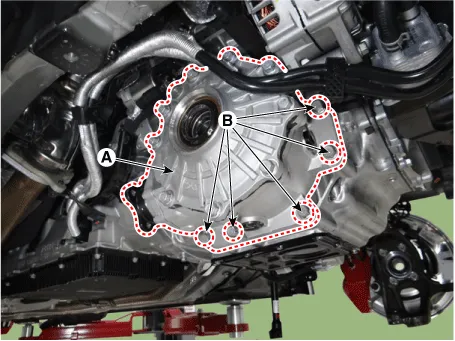
Loosen the front differential bolts (B) and then remove the front differential (A).
|
| 7. |
Install in the reverse order of removal. |
| 8. |
Check the front alignment. (Refer to Suspension System - "Alignment") |
| Disassembly |
[Differential Case Assembly]
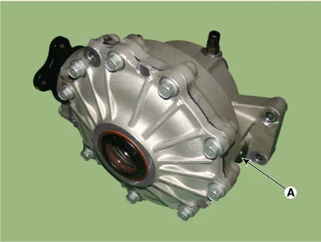
| 1. |
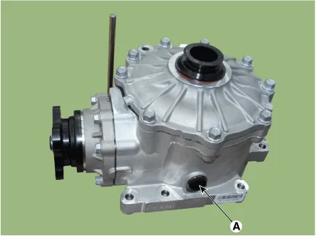
Drain oil by removing the drain plug (A).
|

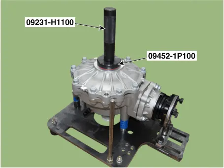
| 2. |
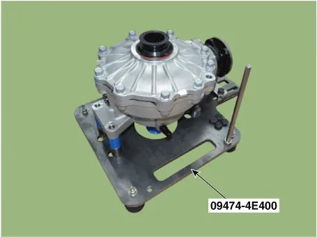
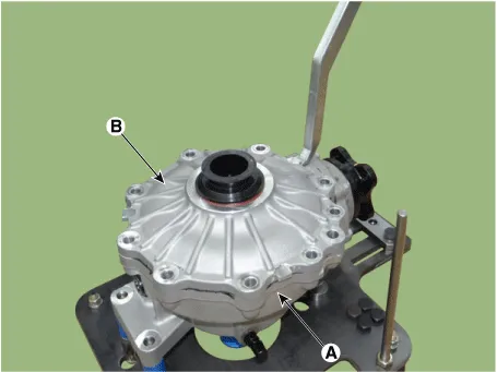
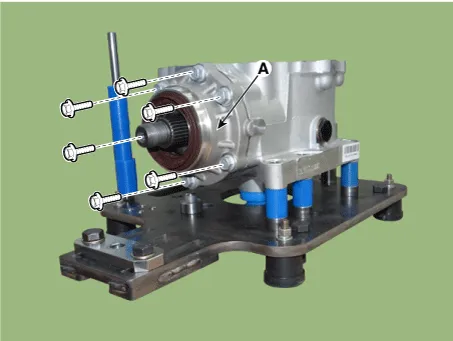
Place the front differential assembly in the SST (09474-4E400).
|
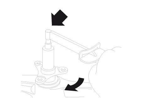
| 3. |
Remove the side oil seal (A) using a screwdriver.
|

| 4. |
Loosen the bolts to remove the cover (B) from the differential carrier.
|
| 5. |
Remove the spacer (A), side bearing race (B) using a hammer and chisel.
|
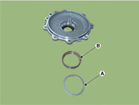
| 6. |
Separate the differential case assembly from the differential carrier.
|
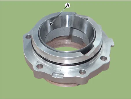
| 7. |
Remove the oil seal (A) from the differential carrier.
|
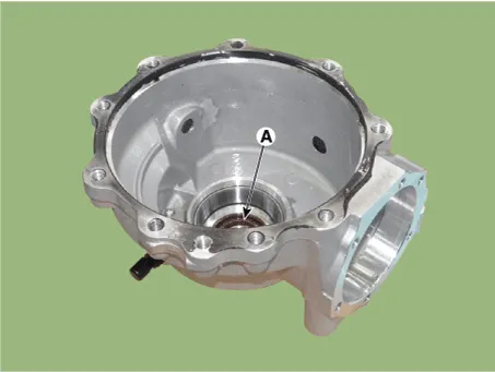
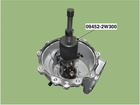
| 8. |
Using the SST (09452-2W300), remove the spacer & bearing race from the differential carrier.
|
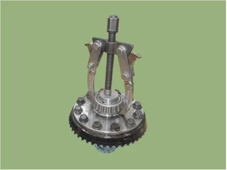
| 9. |
Using the SST (09474-4E200), remove the side bearing.
|

| 10. |
Attach "Left" or "Right" tags to each bearing. |
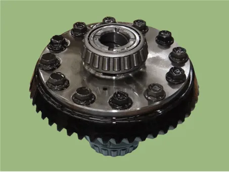
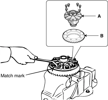
| 11. |
Loosen the bolts and then remove the differential case (A) and ring gear (B).
|
[Pinion drive gear assembly]
| 1. |
Remove the pinion cage.
|

| 2. |
Loosen the bolts and remove the pinion cage(A).
|
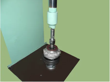
| 3. |
Remove the pinion drive gear from pinion Drive gear assembly using a press.
|
| 4. |
Remove the pinion oil seal (A) & pinion front bearing from the pinion cage by a screwdriver.
|

| 5. |
Using a hammer and chisel, remove the pinion rear bearing race (A).
|
| 6. |
Separate the pinion bearing spacer(A) and pinion front bearing(B).
|

| 7. |
Using a press, remove the pinion rear bearing.
|

| Inspection |
| 1. |
After clearing, check for damage parts or abrasion. Follow the method below, if any are noticed.
|
|||||||||||||||||||||||
| Reassembly |
|
[Pinion drive gear assembly]
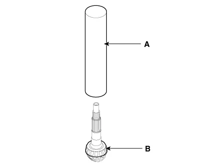
| 1. |
Using the round pipe (A), press in the pinion rear bearing (B).
|
| 2. |
Install the pinion bearing spacer (B) at the pinion drive gear (A).
|
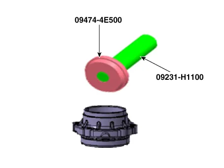
| 3. |
Using the SST (09474-4E500), install the pinion front bearing race.
|
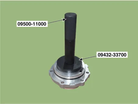
| 4. |
Using the SST (09432-33700), install the pinion rear bearing race.
|
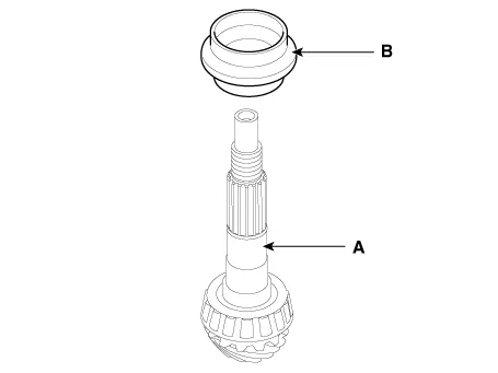
| 5. |
After installing the pinion oil seal(A), install the pinion gear assembly(B) at the pinion cage(C).
|
| 6. |
Install the companion flange.
|
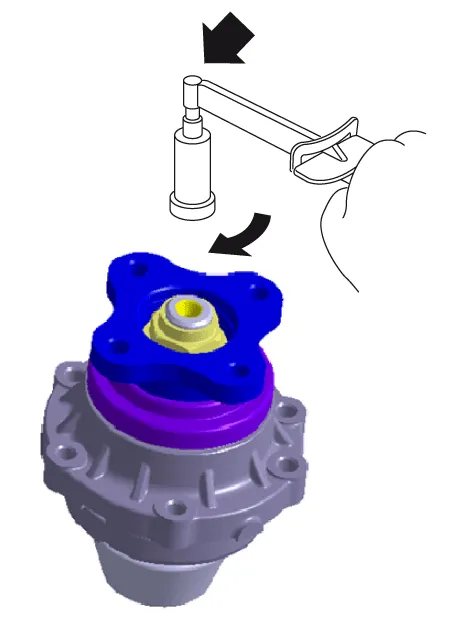
| 7. |
Tighten the pinion lock nut.
|
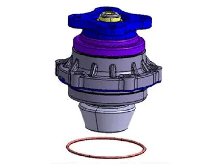
| 8. |
Install the pinion O-ring.
|
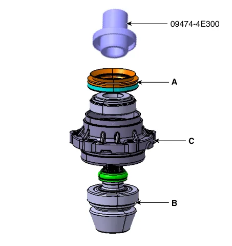
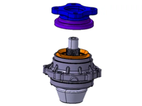
| 9. |
Install the pinion sub assembly (A).
|
[Differential case assembly]
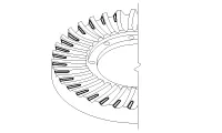
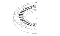
| 1. |
Install the differential case and ring gear.
|
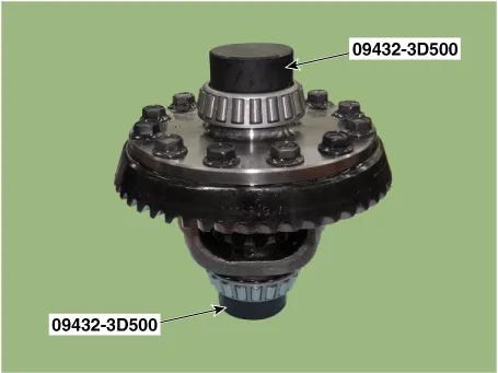
| 2. |
Using SST (09432-3D500), install the side bearing.
|
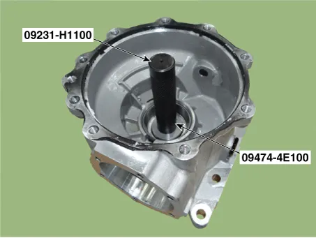
| 3. |
Uisng SST (09474-4E100), install the differential carrier oil seal.
|
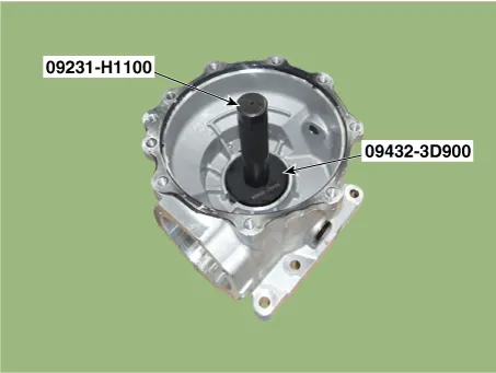
| 4. |
Using SST (09432-3D900), install a spacer and race at the differential carrier.
|
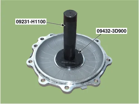
| 5. |
Using SST (09432-3D900), install a spacer and race at the differential carrier cover.
|
| 6. |
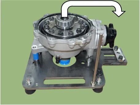
Install the differential case assembly to the differential carrier.
|
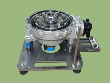
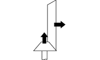
| 7. |
Check the backlash at the companion flange.
|
|||||||||||||||||||||||||||||||||||||||||||


| 8. |
Install the differential carrier cover and then install the oil seal.
|
| 9. |
Measure the total preload.
|
| 10. |
Install the drain plug (A).
|
| 11. |
Install the rear differential assembly to the vehicle. Loosen the filler plug (A) and fill the oil.
|


Other information:
Kia Stinger (CK) 2018-2023 Service Manual: Transmission ranges
The indicator in the instrument cluster displays the shift lever position when the engine start/stop button is in the ON position. However, if the gear is in N (Neutral) or P (Park), the position is displayed on the instrument cluster when the engine start/stop button is in the OFF or ACC position. CAUTION - Transmission To avoid damage to your transmission, do not accelerate the engine in R (Reverse) or any forward gear position with the brakes on.All Kia Air Conditioning Systems are filled with R-1234yf refrigerant. 1.Start the engine. Press the air conditioning button. 2.Set the mode to the position. 3.Set the air intake control to the outside air or recirculated air position. 4.Adjust the fan speed control and temperature control to maintain maximum comfort. • When maximum cooling is desired, set the temperature control to the extreme left position, then set the fan speed control to the highest speed.Categories
- Manuals Home
- Kia Stinger Owners Manual
- Kia Stinger Service Manual
- New on site
- Most important about car
