Kia Stinger CK: LCD windows / Trip information (Trip computer)
Contents:
- Trip Modes
- Fuel Economy
- Accumulated driving information mode
- One time driving information mode
- Digital speedometer
- Smart Shift
The trip computer is a microcomputer- controlled driver information system that displays information related to driving.
✽ NOTICE
Some driving information stored in the trip computer (for example Average Fuel Economy) resets if the battery is disconnected.
Trip Modes
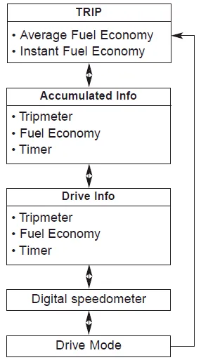
Fuel Economy ➤
Accumulated driving information mode
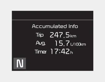
Displays accumulated information starting from mileage/fuel efficiency/time default point.
- Accumulated information is calculated after the vehicle has run for more than 300 meters (0.19 mi).
- If you press “OK” button for more than 1 second after the Cumulative Information is displayed, the information will be reset.
- If the engine is running, even when the vehicle is not in motion, the information will be accumulated.
One time driving information mode

The vehicle will display Driving Information once per one ignition cycle.
- Fuel efficiency is calculated after the vehicle has run for more than 300 meters
(0.19 mi).
- The Driving Information will be reset 4 hours after ignition has been turned off.
So, when the vehicle ignition is turned on within 4 hours, the information will
not be reset.
- If you press “OK” button for more than 1 second after the Driving Information
is displayed, the information will be reset.
- If the engine is running, even when the vehicle is not in motion, the information
will be accumulated.
Digital speedometer
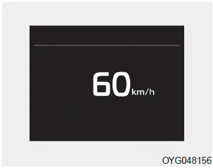
This mode displays the current speed of the vehicle.
Smart Shift
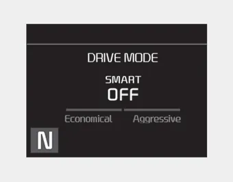
This mode displays the currently selected drive mode.


Other information:
The High Beam Assist is a system that automatically adjusts the headlamp range (switches between high beam and low beam) according to the brightness of other vehicles and road conditions. Operating condition 1.Place the light switch in the AUTO position. 2.Turn on the high beam by pushing the lever away from you. The High Beam Assist ( ) indicator will illuminate.Repair procedures Removal 1. Release the residual pressure in fuel line. (Refer to the Fuel Delivery System - "Release Residual Pressure in Fuel Line") 2. Switch "OFF" the ignition and disconnect the negative (-) battery terminal. 3. Remove the rear seat cushion.Categories
- Manuals Home
- Kia Stinger Owners Manual
- Kia Stinger Service Manual
- Trip Modes
- Fuel Economy
- Accumulated driving information mode
- One time driving information mode
- Digital speedometer
- Smart Shift
- New on site
- Most important about car
Contents
